I run a code club at my local middle school, Ovingham. The school are building an aquaponics system, they have built the hardware but would like to automate the control of the system, this series of blog posts will take you through my attempts to automate this.
Requirements
The school have asked for the following:
- Air temp monitor
- Water monitor
- pH monitor
- public facing website to monitor values (this is being produced by someone else but I will produce a my own as a test site)
- actuator control to open windows (next phase)
Hardware
- Raspberry Pi, as the school have received these great devices from a local Uni they would like to use these
- I will start with just a raspberry Pi, I may move an arduino if performance reduces.
- Temperature sensors
- I have chosen to use two DS18b20 waterproof temp sensors (£8.30 for 5)
Circuit
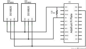
As the DS18b20 sensors use a one-wire interface to communicate with the Raspberry Pi over a serial bus we can add many sensors in parallel, the circuit I am using will therefore contain only the two temperature sensors in parallel and a pull up resistor.
Software
Setting up\testing the DS18b20 sensors
In order to use the sensors we need to load two kernel modules which provide the drivers for the sensors, to do this run the following commands.
sudo modprobe w1-gpio

sudo modprobe w1-therm
The next step is to read from the sensors.
cd /sys/bus/w1/devices/28*
Update 2015: The newer versions of the OS has changed the way I2C and other elements are configured, we now have to turn them on manually. If you run the above and cannot find the directory it may be that I2C is not enabled. Full details can be found here, to get around it run the following:
<p class="p1"><span class="s1">sudo nano /boot/config.txt</span></p>
<p class="p1"># Add the following lines at the bottom of the file</p>
<p class="p1"><span class="s1">dtparam=i2c1=on</span></p>
<p class="p1"><span class="s1">dtoverlay=w1-gpio</span></p>
Save the file and restart the raspberry pi, then run the above commands again, you should now have a directory beginning 28.
The directories for the sensors always start with 28, this therefore takes us into the first directory for the connected sensor, for me this was: /sys/bus/w1/devices/28-000004d0f800
The address of my sensor is 000004d0f800.
To read the value of the sensor we simply need to run the following command:
cat w1_slave
This should produce a result similar to the below, the last 5 digits of the second line provide the temperature reading, to convert this to degrees celsius we need to divide this number by 1000, in this case 20437/1000 = 20.437 degrees C.
47 01 4b 46 7f ff 09 10 93 : crc=93 YES
47 01 4b 46 7f ff 09 10 93 t=20437
We now need to check the second sensor, to do this we can move back up a directory to ensure that two sensors are connected
cd ..
ls
From this I received the below output
28-000004d0f800 28-000004d11b6c w1_bus_master1
We can therefore see there are two sensors connected, so we’ll now check the operation of the second sensor, move into teh directory and run the command used previously
cd 28-000004d11b6c
cat w1-slave
This gives me the output
40 01 4b 46 7f ff 10 10 1d : crc=1d YES
40 01 4b 46 7f ff 10 10 1d t=20000
My sensors are therefore working correctly and we can move onto setting up the code to read the results automatically.
Automating the sensor reading
We want to be able to automatically read the values, to do this we use a simple python script.
First of all navigate back ‘home’ so we know where we are saving our files and the create a new file
cd ~

sudo nano checktemp.py
Within the code we will use functions to perform the following:
- findDevices
- This will loop through the devices directory and locate each device that’s installed
- takeReading
- this function will take a reading from the device by reading the last 5 characters of the second line
Our main routine will load the kernels, loop through the kernels and load and print the values
#!/usr/bin/env python

import os, glob

#function to locatethe sensor directories, returns a list of sensor directories
def findDevices (path, filter):
     for dirs in glob.glob(path):
     #check for the master directory as we don't want to search this for devices
         if not "w1_bus_master1" in dirs:
             yield dirs

#function to read the device value, assumes all devices use last 5 digits of 2nd line
def takeReading(device):
     try:
         fileobj = open(device, 'r')
         lines = fileobj.readlines()
         fileobj.close()
     except:
     return None

     #check the sensor status
     status = lines[0][-4:-1]
     #if the status is OK then read the device value
     if status=="YES":
         # read the last 5 characters from teh second line
         value=lines[1][-6:-1]
         return value
     else:
         return "error device: " + device

#Main code
# load the kernels for the sensor
os.system('modprobe w1-gpio')
os.system('modprobe w1-therm')

# get the list of device locations
for device in findDevices('/sys/bus/w1/devices/*','28*'):
         # create the device filename, appending the filename to the path
         deviceFile = device + '/w1_slave'
         #open the file containing the sensor data
         print(takeReading(deviceFile))
Logging the values in a database
Now we have the data being read automatically we’d like to store the information centrally for analysis. This section will send the readings to a web service that I have created, which will allow us to then develop a website to present the information.
The web service is a simple PUSH interface that can be accessed to submit the key bits of information:
- Device ID
- Time of Reading
- Reading Value
To call webservices we need to use two libraries, these should be added to your tempcheck.py using statement so it now looks like the below:
import os, glob, urllib, urllib2, datetime
from datetime import datetime
It’s then simply a case of adding the below code to the main section of the script, within the loop so we can post the values for each device.
url = "<web service address"
 values = dict(device_id=device[-15:], reading_d_t=datetime.now(), reading=takeReading(deviceFile))
 data=urllib.urlencode(values)
 req = urllib2.Request(url,data)
 rsp = urllib2.urlopen(req)
 content = rsp.read()
The values section should contain the values required in the POST call, for my service I am sending the device ID, the datetime the reading was taken and the reading.
You can now run the python script and check that a new value has been added to the web server.
Scheduling the script
So we now have a script that records the readings and sends them to a webservice to log in a database, obviously we don’t want to manually run this script to get readings, instead we will schedule the script to run every 15 minutes using a tool called cron. Run the following command to create a cron scheduler:
crontab -e
You should see an error stating that a new table is being created and a blank file should open with some cron formatting information at the top. This is the file within which you can add commands to run periodically, we want to run teh check every 15 minutes so add the following line:
*/15 * * * * ./checktemp.py
This tells cron to run the checktemp script every 15 minutes, you will probably be in nano so press Ctrl+x to exit and save the file.
Now wait for 15 minutes and check that the readings are being sent to the web service and that is it.
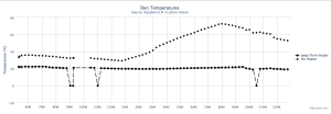
A screenshot of the site is shown below, note some of the ‘drops’ I am looking at what can be done but this seems to be an issue with the sensors.
Improvements
This has gone through the basics of setting up a sensor, there are various improvements I would like to make and I will blog these in separate posts in future:
- Error handling, what happens if the web service is down?
- Security, how do we ensure that the web service is receiving trusted information?
- Configuration, how can we build the logger so that it automatically picks up new devices both on the Rapberry Pi and the web site


This looks great!! I would imagine that other sensors such as a ph sensor will also return readings in the same format with the last 5 digits of the second line giving you the reading?
Great tutorial though!
Thanks
Thanks!
I have the pH sensor built, it actually reads the values over the serial port and posts to the web server in the same format, I’ve moved that logic into a separate method. I just need to write it up but want to get the full solution developed, including the callibration routine, which I’d like the system to lead the user through using LEDs as the intention is to have the RPi headless.